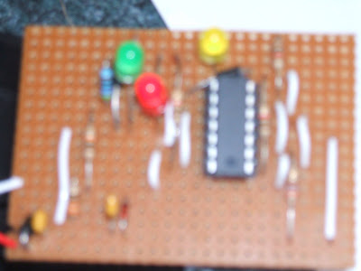
Schematic :
Design :
Component List :
D1 9.1v Zener diode
D2 1N4001
D3 1N4001
C1 0.1uf capacitor
C2 0.1cu capacitor
D1 9.1v Zener diode
D2 1N4001
D3 1N4001
C1 0.1uf capacitor
C2 0.1cu capacitor
R2 1000Ω carbon pile resistor
R3 1000Ω carbon pile resistor
R4 1000Ω carbon pile resistor
R5 340Ω carbon pile resistor
R6 10KΩ carbon pile resistor
R7 270Ω carbon pile resistor
R8 470Ω carbon pile resistor
LED 1 9.5ma 1.8v (red)
LED 2 9.5ma 1.8v (yellow)
LED 3 9.5ma 1.8v (green)
Ic Quad Op-amp LM324 3v - 30v.
Circuit board 2.54mm grid.
Calculations :
R2, R3, R4 = V/I
Vs 12v - 1.8v = 10.2v/9.5ma = 1073.6 so
R2 = 1000Ω
R3 = 1000Ω
R4 = 1000Ω
R5 = 12v - 0.7 - 9.1v = 2.2v then 9.1/1000 = 0.91ma + 5.6ma = 0.00651 = 2.2/0.00651 = 337.3 so
R5 = 340Ω
R8 = Vd = Rabove/Rt.Vin so 9.1 - 0.63 = Vd 8.47 = 1000/Rt x 9.1 = Rt = 9.1x1000/8.47
Rt = 10743.8Ω Rt = R6 + R7 + R8 so R7 + R8 = 744Ω
Vd = 0.63 - 0.23 = 0.4v Vd = Ra/Rt.Vin = 0.4 = Ra/744 x 0.63 = 0.4/0.63 = Ra/744 =
0.6349 x 744 Ra = 472.3
R8 = 470Ω
R7 = 744 - 472 = 272 so
R7 = 270Ω
Test Procedure :
My testing point was 0.5v so yellow LED was glowing. Then I volt droped the circuit components.
Vd =
D1 zener = 9.3v D2 = 0.6v D3 = 0.6v
C1 = 11.6v C2 = 9.3v
R2 = 0v R3 = 7.5v R4 = 0v R5 = 2.2v R7 = 0.2v R8 = 0.4v
LED 1 = 3.4v yellow LED 2 = 1.2v red LED = 1.2v green
Circuit Explanation :
This circuit replicates how the oxygen sensor operates. From 0 - 0.23v from an inverted amplified signal the green LED was on representing a lean mixture. From 0.23 - 0.63v The green switched off and the yellow LED switched on from a inverted signal which represents a normal mixture. From 0.63 - 0.99v the yellow was switched off from the non- inverting signal and the red LED switched on representing a rich mixture.
Problems :
The red LED 2 would not switch on so I checked the layout of components that would effect the LED and found the diode from the Vout of the first op-amp was positioned after the LED and the resistor. But it needed to be from Vout to between the LED and the resistor once I resolderd the diode in the correct place the circuit was all good.
Reflection :
If I would do this circuit again I would study the data sheet for the LM324 and learn more so I could design a more professional layout and not spend so much time changing bridge wires and resistors.


